INTRODUCTION
An Apache 700XR unit can switch a relay (or multiple relays on the Quattro module). this is enabled by ringing the unit. When the phone number is programmed into the unit, the Apache 700XR will recognise the number and switch the relay.
This manual describes the installation and operation of the following three Gsm modules:
– Apache 700XR 2nd Generation
- Reception via 2G network
- Up to 2000 users
- 400 special users
- 1 relay
- Programmable via SMS, RS232/USB-cable, Modem and IP
– Apache 700XR 3rd Generation
- Reception via 2G and 3G network
- Up to 2000 users
- 400 special users
- 1 relay
- Programmable via SMS, RS232/USB-cable, Modem and IP
– Apache 700XR 3rd Generation Quattro
- Reception via 2G and 3G network
- Up to 4000 users
- 400 special users
- 4 relay
- Programmable via SMS, RS232/USB-cable and IP
- Week clock
- Including separate Quattro relay module
CONTENTS
- SIM card
- Power supply
- Reception
- Apache 700XR 2nd Generation and Apache 700XR 3rd Generation
- Apache 700XR 3rd Generation Quattro + relay module
- External relay connection (for 2nd Generation and 3rd Generation)
6. Programming via RS232/USB-cable, Modem or IP
DETERMINING WHICH UNIT YOU HAVE
The following sticker will be located on the unit:
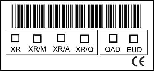
This will tell you which unit you have. The first four squares indicate whether it is a normal unit, a modem unit, an alert unit or a Quattro unit. If QAD is ticked, it means that you have a 2nd Generation XR unit. If EUD is ticked, it means that you have a 3rd Generation XR unit.
1.INSTALLATION REQUIREMENTS
In order for the GSM module to work correctly, it is important that you comply with all the requirements! (Please note that the operation of the unit is dependent on the correct functioning of the GSM network according to the indicated specifications).
SIM CARD
The unit works with both a subscription and prepaid call SIM cards. If you are using a prepaid card, you must ensure that your phone credit does not expire or that you can use it for as long as possible. Some prepaid cards have to be charged a few times a year if you wish to keep on using them. Make sure that your provider has activated the SIM card before you place it in the unit and ensure that the pin-code, voice mail and call-waiting are switched off.
If you opt to programme via the modem (chapter 6), the SIM card in the modem and the SIM card in the unit must both be equipped with number recognition and CSD (Circuit switched Data). If you opt to programme via IP, the SIM card must also have a fixed IP address and a data subscription.
NB!
The Apache 700XR 2nd Generation only works on the 2G network. The Apache 700XR 3rd Generation works on the 2G and 3G network.
POWER SUPPLY
The power supply for the Apache must be at least 12V Dc and a maximum of 24V Dc. The use of a fuse in the Apache is advised if you are using vehicles with 24V charge, such as lorries. The power supply must correspond to en60950 guidelines.
- Supply voltage 12V DC – 24V DC
- Power supply: minimum 1.2A @12V DC
- Maximum switch output internal relay = 1A @ 30V DC
RECEPTION
The unit must be able to receive the Gsm network from your provider. Install the unit in a location with sufficient signal from your network provider. If the reception is not good, you can connect the antenna with a 3 meter cable in order to maximise reception.
2.QUICK START
- Place an activated SIM card or SIM card without pin-code, voicemail or call-waiting into the unit.
- Then connect the power supply.
- The red LED will light up briefly and then go out.
- After around 25 seconds, the red LED will begin to blink.
- The green LED will come on around 60 seconds later and the red LED will blink every 3 seconds; the unit is now ready to be called.
- Programme your telephone number into the unit via an sms or the software.
- You can now switch the relay by calling the number of the unit.
NB: 3rd Generation units will start up more quickly than set out above.
3.STATUS OF THE LED
The status of the built-in LEDs can be read off to ensure that the unit is working correctly. Below, you can see the LED indications and the corresponding meanings.
Green LED gives the status of the internal software and the GSM network
- On all the time Unit ready for call/registered on the network
- Blinking quickly (between 0.5 and 1 sec) SIM card is not recognised/SIM card is not working/No SIM card in unit
- Blinking occasionally (1 sec on 0.3 sec off) Time has not been set on the unit
- Temporarily off Unit’s relay is switching
- Permanently off Unit is off
Red LED indicates the hardware status of the unit
- On all the time Call underway
- Blinking quickly (between 0.5 and 1 sec) Hardware error
- Blinking slowly (3 sec) Unit has started up and hardware is ok
- Permanently off Unit is off
If the green LED is on all the time, it indicates that the Apache is ready for use and that it can be programmed.
THE GREEN LED MUST BE ON ALL THE TIME IN ORDER TO SWITCH THE RELAY OR MAKE THE CONNECTION VIA THE SOFTWARE.
If the green LED blinks, a working SIM card has not been installed or there is no contact with the provider of the SIM card.
The red LED must blink slowly; this indicates that the unit is completely active.
If the green LED stays on for a long time and blinks every now and then, the time has not been set on the unit and it won’t function properly. In order to resolve this, send an SMS with P.1234CU to the unit or set the ‘clock update sms’ (via the software). If you choose the latter option (via the software), you must then reboot the unit by pressing the ‘reset’ button on the front of the unit until the green leD blinks rapidly. The unit will then re-start.
4.1.CONNECTION DIAGRAM 2ND & 3RD GEN
Apache 700XR 2nd Generation and Apache 700XR 3rd Generation
We advise you to use the adapter (supplied) to supply power to the unit. If you do not want to use this, you must connect the red and black wires.
NB: You must never connect the adapter and the wires simultaneously!
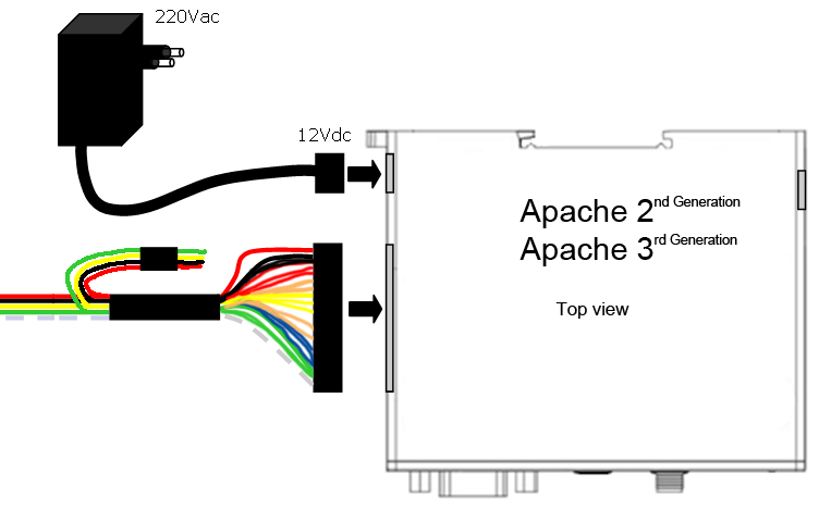
- Red
- Black
- Yellow
- Green
- White
- Red: Input / Output power 12-24 VDC
- Black: Ground
- Yellow: Not used
- Green: relay (potential-free switch contact)
- White: relay (potential-free switch contact)
NB: If you use the adapter, you must isolate the red and black wires!
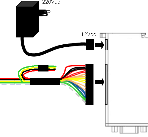
4.2.CONNECTION DIAGRAM QUATTRO
Apache 700XR 3rd Generation Quattro
We advise you to use the adapter (supplied) to supply power to the unit. If you do not want to use this, you must connect the red and black wires.
NB: You must never connect the adapter and the wires simultaneously!
The Apache Quattro module came with a special 24-pin cable. Not every connection is used, so look at the following chart which wires you need to connect. Below the image of the relay module you find an indication for which wire should be connected to which connector.
Note: It is recommended that the wires that aren’t used are bind together and bend, as seen in the picture below.

- 5 (Blue)
- 6 (Blue)
- 7 (Blue)
- 14 (White)
- 23 (Black)
- 24 (Red)
12 + 13
Numbers wires:
- not in use
- not in use
- not in use
- not in use
- not in use
- s2
- s3
- s4
- not in use
- not in use
- not in use
- not in use
- connect to wire 13
- connect to wire 12
- s1
- not in use
- not in use
- not in use
- not in use
- not in use
- not in use
- not in use
- not in use
- V
- V+
Apache 700XR 3rd Generation Quattro relay module

- Output NC
- Output COM
- Output NO
24 23 14 5 6 7 / /
Relay outputs (Apache 3rd generation Quattro)
The Apache 3rd Generation Quattro is equipped with a module with 4 relay outputs. The connections for these outputs are located on the relay unit that is connected to the Apache 3rd Generation Quattro via the special connector cables.
- Maximum switch voltage per relay = 10A @ 250 V AC / 10A @ 30 V DC
- Relay 1: Normally Open (NO/NC)
- Relay 2: Normally Open (NO/NC)
- Relay 3: Normally Open (NO/NC)
- Relay 4: Normally Open (NO/NC)
The switch duration per relay can be set individually between 1 and 60 seconds. The relay can be switched separately by calling the unit or sending an sms.
When a connection is made to the unit, the user can choose on their telephone which relay must be switched by pressing the corresponding figure on the mobile phone. This functionality can be set via the software and can be set per user. The corresponding sms command can be found in the following chapter.
NB
If a user is authorised to switch one relay, only the allocated relay will switch; the connection will not be made first. The unit will refuse the call via number recognition. If a user is authorised to switch more than one relay, a connection will be made and he must choose which relay is switched.
If users can choose which relay is switched, the provider will make a charge because the mobile network is being used.
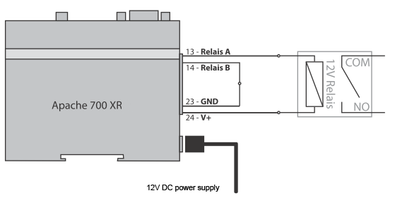
External relay connection (2nd Generation and 3rd Generation)
If the relay has to switch a (control) voltage, you must use an external relay when commissioning. If the external relay breaks down due to frequent switching, you can simply connect a new external switch relay and do not need to replace the unit. The supply is internally connected to pin 23 (GnD) and pin 24 (V+)
- Connect Pin 24 (V+) directly to the relay
- Connect pin 23 (GND) with pin 14 (relay B)
- Connect pin 13 (relay a) with relay
Connection examples
Relay output connected to switch relay or pulse relay
Internal relay can switch a maximum of 30V/1 ampère
5.PROGRAMMING VIA SMS
1.1 Password
Every sms starts with P:password (standard 1234) Example: P.1234A.0541122333.0544455666 the command P. the password is 1234 the command A. is add new phone number to the list, in this example: 0541122333 and 0544455666
1.2 Add new phone number
A.phone number,phone number,… add new phone numbers to the phone list Example: P.1234A.0547512152.0525874525 add 0547512152 and 0525874525 to the phone list. When more phone numbers have to be added, than put a dot between the phone numbers, all SMS size can be used.
1.3 Add special new phone number
AS.phone number.1.from time,to time week days,… Add one new special phone number to the special list with specific hours during the week days. the “from time” and the “to time” syntax is HHmm (with no spaces)
- Example 1: P.1234AS.058126248.1.1130.1540.135 Phone number 058126248 will be allowed to enter from 11:30 to 15:40 on Sunday, tuesday and thursday ( 1234567 weekdays starting with sunday)
- Example 2: P.1234AS.058126248.1.2300.0200.24 Phone number 058126248 will be allowed to enter from 23:30 to 02:00 on monday and Wednesday.
AS.phone number.3.entries amount,… add one new special phone number to the special list with limited entries amount.
- Example 1: P.1234AS.058126248.3.6 Phone number 058126248 will be allowed to enter 6 times
- Example 2: P.1234AS.058126248.3.11 Phone number 058126248 will be allowed to enter 11 times
1.4 Delete phone number
D.phone number.phone number,… Delete phone numbers from regular phone list. Example: P.1234D.0542684284.0542358721 Phone number 0542684284 and 0542358721 deleted from the regular phone list, put comma between the phone numbers, can use all SMS size. When more phone numbers have to be added, than put a dot between the phone numbers, all sms size can be used.
1.5 Delete special phone number
Ds.phone number.phone number,… Delete phone numbers from special phone list. Example: P.1234DS.0542684284.0542358721 Phone number 0542684284 and 0542358721 deleted from the special phone list. When more phone numbers have to be added, than put a dot between the phone numbers, all sms size can be used.
1.6 Set puls time (advanced) (only 2nd and 3rd Generation)
GOD.gate open delay,… Set the time of the pulse when calling to the unit, Maximum 60 seconds. Example: P.1234GOD.7 set the gate open to 7 second delay.
1.7 Set puls time (advanced) (only Quattro)
GOD.gate open delay relais 1, relais 2, relais 3, relais 4,… Set the time of the pulse when calling to the unit, Maximum 60 seconds. Example: P.1234GOD.7,5,3,1 set the gate open to: Relay 1: 7 seconds Relay 2: 5 seconds Relay 3: 3 seconds Relay 4: 1 seconds
1.8 Clock update
CU,… Clock update, update the unit’s clock from the SMS send time. Example: P.1234CU
1.9 New password
NP.new,… password sets new password to the Apache 700XR unit (the CSD password infect also). (be careful with it, when lost, the module have to get back to the manufacturer) Example: P.1234NP.4321 change the password to 4321
1.10 Enable/Disable
EN.1.0,… set the Apache 700XR unit to enable or disable. Example 1: P.1234EN.1 enable the Apache 700XR unit Example 2: P.1234EN.0 Disable the Apache 700XR unit.
1.11 Get unit information
Info,… Get information about the Apache 700XR unit: ·
- Amount of numbers in the phone list
- Amount of numbers in the special phone list
- Reception level
- Apache 700XR unit enable\Disable
Example: P.1234INFO
1.12 Reset unit
Reset,… Reset the Apache 700XR unit from remote Example: P.1234RESET
1.13 Enable/Disable phone list
OPEN.1.0,… Enable/Disable phone list Example 1: P.1234OPEN.0 enable phone list (only phone numbers that are in de phone list can disable the Apache 700XR unit) Example 2: P.1234OPEN.1 Disable phone list (all phone numbers can disable the Apache 700XR unit).
1.14 Requesting unit IP-address
IP? Requesting the IP-address of the unit Example: P.1234IP?
1.15 Switching the relay (Only Quattro)
o + number of relay Example 1: O1 this will switch relay 1 Example 2: O3 this will switch relay 3
1.16 Adding phone number, name and relay (Only Quattro)
AN.phone number.username,… this will add the phone number with a name that can use only relay 1 Example 1: P.1234AN.0547512152,Mark Add the phone number 0547512152 with user name “Mark”, who can switch relay 1.
AN.phonenumber.username.relay1.relay2.relay3.relay4.sms,… This will add the phone number with a name. You can choose which relay can be switched and whether you want to receive an notification SMS upon activation of the relay or not. Example 2: P.1234AN.0547512152,Mark,1,1,0,0,1 add the phone number 0547512152 with user name “mark” that can activate relay 1 and relay 2 and the unit will send SMS notification when he opens the gate.
1.17 Set APN (Only 2nd generation unit, from XR version 2.1.8)
GPRS.<EN>,<FIREWALLIP>,<APN>,<USERNAME>,<PASS> The parameters are: EN is 1 or 0. For activating APN, set 1. For disabling APN set 0. FIREWALLIP is the Firewall IP. APN is the APN number. username is the username (not always necessary). Pass is the password (not always necessary). You can obtain all required data from your provider. Example: P.1234GPRS.1,62.133.1.0,advancedinternet,user,user this sets the APN.
NOTE: If you don’t supply a certain field, you will still have to send the comma. Example: P.1234GPRS.1,,advancedinternet,,
6.PROGRAMMING VIA SOFTWARE USING RS232/USB, MODEM OR IP
In order connect with the unit via the software using the RS232/USB cable (all units), the modem (only 2nd and 3rd Generation) or IP (all units), we refer you to the special software manual that is supplied with the software.
7.TECHNICAL DATA
- GSM frequency 2nd Gen.: Quad band: GSM 850/900/1800/1900MHz
- GSM frequency 3rd Gen.: GSM\UMTS-HSPA 800/850/900/ASW/1900/2100MHz network: 2G with 2nd Generation and 2G+3G with 3rd Generation
- Power supply: 12-24V Dc operating temperature: -20°c tot +55°c
- Dimensions: 98mm x 82m x 30m Weight: 160g
- RoHS, WEEE: All hardware components are fully compliant with the eu RoHs and Weee Directives
Supply voltage requirements:
- Input voltage range 12V DC – 24V DC
- Nominal voltage 12V DC
- Power Supply current rating: min. 1,2A @12V DC
- Power Supply ripple: max. 120mV
- Input current in idle mode: 20mA @ 12V DC
- Input average current in communication mode: 100mA @ 12V DC
Internal relay:
- Maximum voltage = 1A @ 30V DC.
- The relay is normally open (NO).
8.SAFETY RECOMMENDATIONS
READ CAREFULLY
It is responsibility of the user to enforce the country regulation and the specific environment regulation. Do not disassemble the product; any mark of tampering will compromise the warranty validity. We recommend following the instructions of the hardware user guides for a correct wiring of the product.The product has to be supplied with a stabilized voltage source and the wiring has to be conforming to the security and fire prevention regulations. The product has to be handled with care, avoiding any contact with the pins because electrostatic discharges may damage the product itself.
The use of this product may be dangerous and may have to be avoided in the following areas: Where it can interfere with other electronic devices and where there is risk of explosion such as gasoline stations, oil refineries, etc.
Same cautions have to be taken for the SIM, checking carefully the instruction for its use. Do not insert or remove the SIM when the product is in power saving mode. he system integrator is responsible of the functioning of the installation; therefore, care has to be taken to the external components of the module.
Should there be any doubt, please refer to the technical documentation and the regulations in force. Every module has to be equipped with a original antenna with specific characteristics. The antenna has to be installed with care in order to avoid any interference with other electronic devices and has to guarantee a minimum distance from the body (20 cm). In case of this requirement cannot be satisfied, the system integrator has to assess the installation against the SAR regulation.
The European Community provides some Directives for the electronic equipments introduced on the market. All the relevant information’s are available on the european community website:
http://ec.europa.eu/index_en.htm
Parts United B.V. declares that the product, Apache 700XR EZ863 PY Terminal, Fulfills the essential requirements of Directive 89/336/EEC. The following standards were applied: emc en 55022:1994 + a1:1995 + a2:1997 en 55024: 1998 + a1:2001 + a2:2003 EN50081-1 : 1998 Emission test EN55022 Class B en55024 : 1998 Immunity tests safety Iec 60950-1:2001. The complete declaration of conformity is available on the website: http://www.apache700xr.com/ce